The ESP32 is one of the most accessible ways to build a hardware frontend for LiveKit Agents. An ESP32-S3 with a microphone and speaker can join a LiveKit room, stream audio to a cloud-hosted agent, and play back the agent's response — all over WiFi with sub-100ms transport latency.
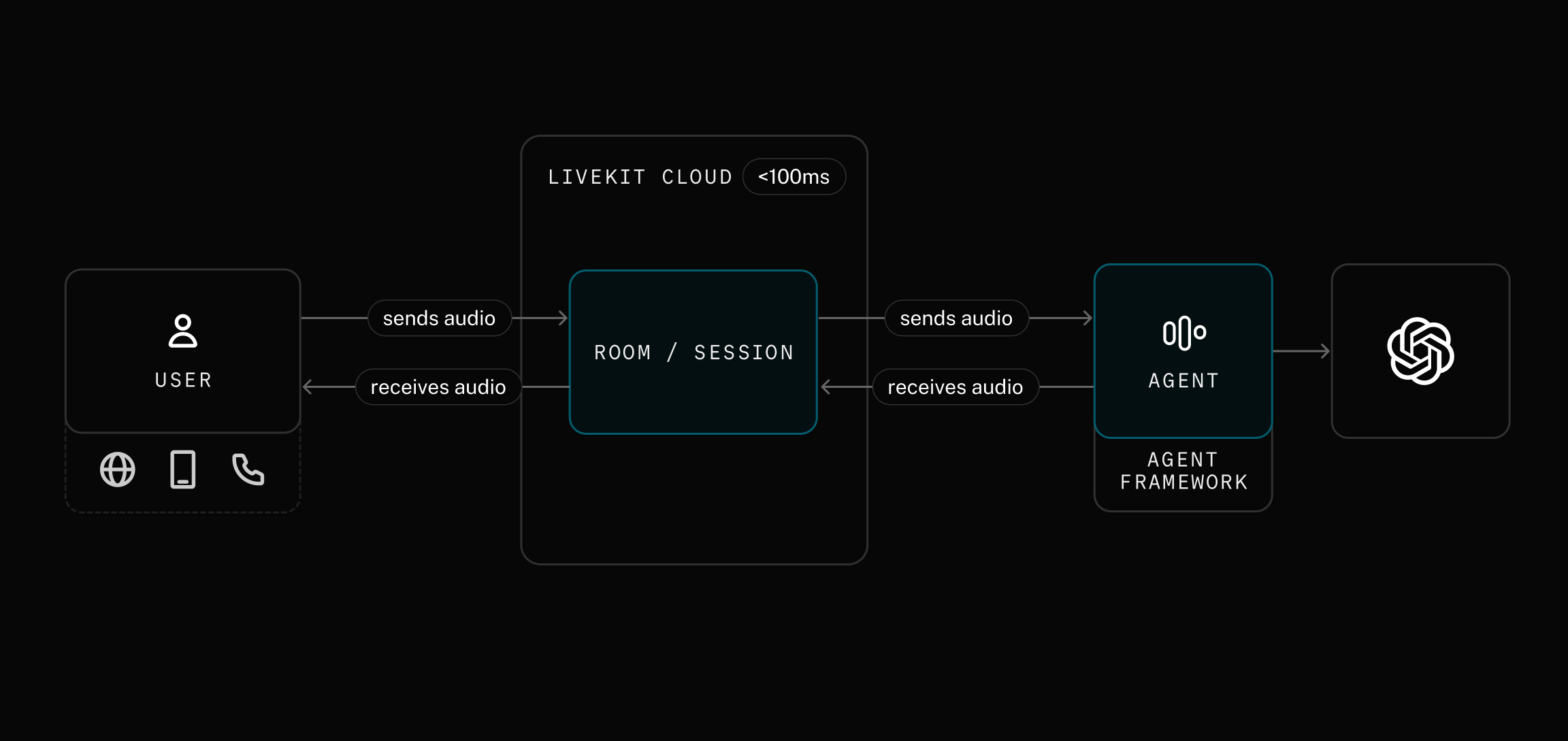
In the diagram above, the USER box represents any LiveKit client — a browser, a mobile app, a phone call, or an ESP32. Your ESP32 is just another client: it connects to a LiveKit room the same way a web browser or mobile app would. The agent on the other side of that room sends and receives audio without knowing (or caring) what kind of device it's talking to. This means you can build a dedicated hardware voice interface for any LiveKit agent — a smart speaker, a robot, an intercom — using the same agent backend you'd use for a web app.
The LiveKit ESP32 SDK ships with examples for reference boards like the ESP32-S3-BOX-3 and ESP-Korvo-2. But if you're building a product on your own hardware — or evaluating on a dev board that isn't in the examples — you need to adapt the SDK to your pin configuration and audio codecs.
This post walks through the full process: read the schematic, map the pins, initialize the audio hardware, and get the ESP32 connected to a LiveKit room where it can talk to an agent. The Waveshare ESP32-S3-Touch-LCD-1.83 serves as a concrete example. It's affordable (~$16), widely available, and uses the ES8311 + ES7210 codec pair — the same audio front-end found on Espressif's own reference boards. Its compact form factor and battery header also make it a good candidate for embedding in your own product enclosure. The board has a published BSP, but you'll configure everything manually here to see how it works on any board.
What you'll need#
- Waveshare ESP32-S3-Touch-LCD-1.83 (or your own ESP32-S3 board with I2S audio).
- A small speaker with MX1.25 connector (the board used here has a speaker connected already).
- ESP-IDF 5.4 or later (install guide).
- A LiveKit Cloud account (free tier works) or a self-hosted LiveKit server.
- USB-C cable.
- Python 3 with the
livekit-apipackage (pip install livekit-api) — for generating tokens.
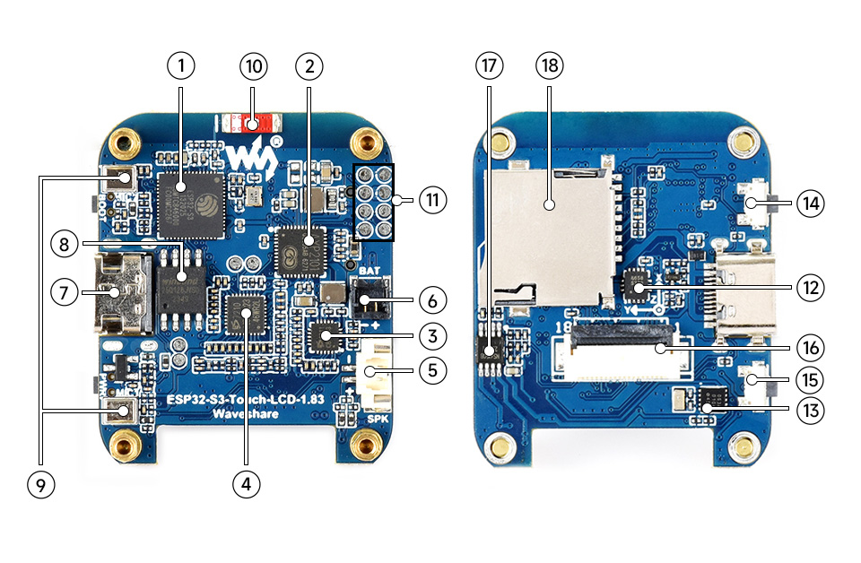
Meet the board#
| # | Component | Description |
|---|---|---|
| 1 | ESP32-S3R8 | Dual-core SoC, 240 MHz, 8 MB PSRAM |
| 2 | AXP2101 | Power management IC (controls codec power rails) |
| 3 | ES8311 | Audio DAC — drives the speaker |
| 4 | ES7210 | Audio ADC — captures from the dual-mic array |
| 5 | MX1.25 speaker header | Connect an external speaker here |
| 6 | Battery header | 3.7 V lithium battery (optional) |
| 7 | USB-C port | Flashing and serial monitor |
| 8 | 16 MB NOR flash | Program and data storage |
| 9 | Dual microphone array | Two MEMS mics for voice capture and echo cancellation |
| 10 | Onboard antenna | 2.4 GHz WiFi and Bluetooth 5 LE |
| 17 | NS4150B amp | Class-D speaker amplifier (needs GPIO enable) |
Callout numbers match the photo above. Components not listed (11-16, 18) are for the LCD, touch controller, TF card slot, and other peripherals not needed for audio.
The ES8311 + ES7210 codec pair is the same audio front-end used on the ESP32-S3-BOX-3 and Korvo-2 reference boards — well-supported drivers, proven AEC performance, and plenty of example code to reference. The only difference on this board is the GPIO pin assignments, which is exactly the problem you need to solve.
Step 1: Extract pin assignments from the schematic#
Download the board schematic from the Waveshare wiki. You need to find three things: I2S bus pins, I2C bus pins, and codec I2C addresses.
I2S bus — the audio data path#
Open the Codec block in the schematic. The ES8311 (U9) has the I2S signals labeled on its pins:
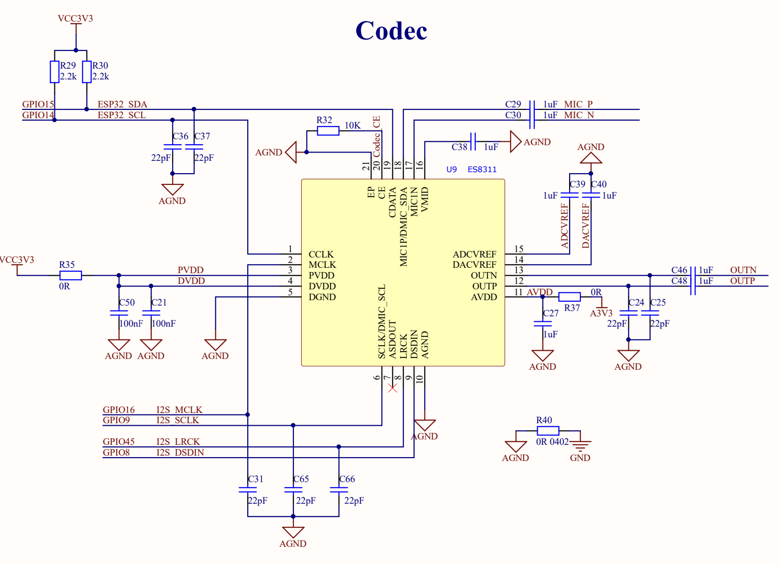
GPIO16→I2S_MCLK— master clock to both codecs.GPIO9→I2S_SCLK— bit clock.GPIO45→I2S_LRCK— word select (left/right clock).GPIO8→I2S_DSDIN— serial data into the ES8311 DAC (playback).
Now look at the ADC block for the ES7210 (U12):
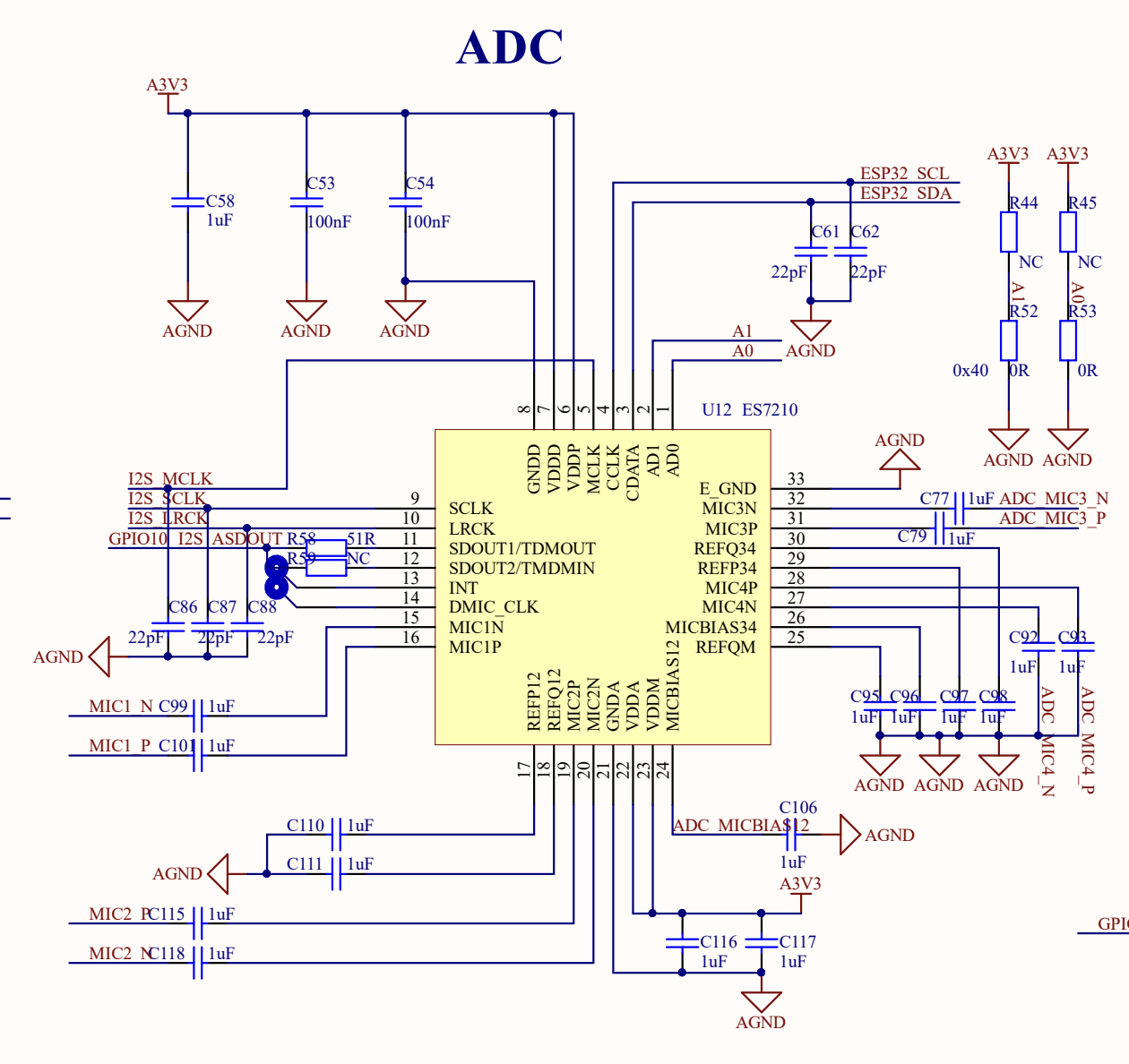
The ES7210 shares the same clock lines and adds one more data pin:
GPIO10→I2S_ASDOUT— serial data out of the ES7210 ADC (recording).
I2C bus — codec control#
Both codecs are configured over I2C. The schematic shows them sharing a bus:
GPIO14→ESP32_SCLGPIO15→ESP32_SDA
This bus is shared with the touch controller, RTC, IMU, and PMU. Each device has a unique address, so they coexist without conflict.
I2C addresses#
The ES8311 CE pin is pulled low → 7-bit address 0x18.
The ES7210 AD0 and AD1 pins are tied to ground → 7-bit address 0x40.
Speaker amplifier#
The NS4150B class-D amplifier is enabled by GPIO46 (PA_CTRL). If you don't drive this pin high, the speaker stays silent — a common gotcha.
Cross-referencing with the GPIO table#
The schematic includes a GPIO allocation table. Use it to verify:
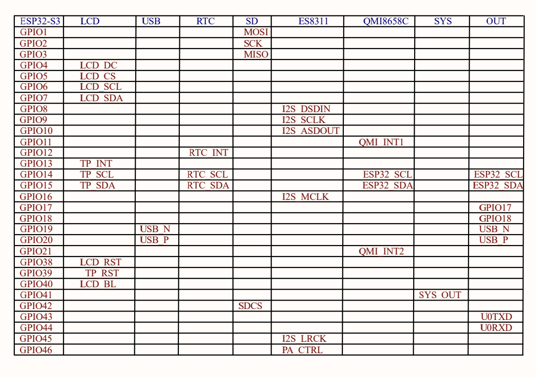
Pin summary#
I2S bus:
| Signal | GPIO | Direction | Description |
|---|---|---|---|
I2S_MCLK | 16 | Out | Master clock to both codecs |
I2S_SCLK | 9 | Out | Bit clock (BCLK) |
I2S_LRCK | 45 | Out | Word select (WS) |
I2S_DSDIN | 8 | Out | ESP32 → ES8311 (playback) |
I2S_ASDOUT | 10 | In | ES7210 → ESP32 (recording) |
I2C bus and addresses:
| Signal/Device | GPIO / Address |
|---|---|
ESP32_SCL | GPIO 14 |
ESP32_SDA | GPIO 15 |
| ES8311 (DAC) | 7-bit 0x18 / 8-bit 0x30 |
| ES7210 (ADC) | 7-bit 0x40 / 8-bit 0x80 |
| AXP2101 (PMU) | 7-bit 0x34 |
| PA enable | GPIO 46 |
Watch out: 7-bit vs 8-bit I2C addresses. The
esp_codec_devdriver expects 8-bit (left-shifted) addresses inaudio_codec_i2c_cfg_t.addr. It internally right-shifts by 1 to get the 7-bit address. If you pass the raw 7-bit address from the datasheet (e.g.0x18), the driver talks to address0x0Cand you'll get NACKs. Use theES8311_CODEC_DEFAULT_ADDR(0x30) andES7210_CODEC_DEFAULT_ADDR(0x80) macros.
Step 2: Initialize the hardware#
The SDK's reference examples use a codec_board component that reads board configs from a file. That works for supported boards but hides the initialization sequence. For custom hardware, it's more reliable to initialize each peripheral directly.
The order matters: I2C → PMU → I2S → codecs. The AXP2101 PMU controls the power rail that feeds the codecs. If you skip it, every I2C transaction to the codecs will NACK.
2a. I2C bus#
1#define BOARD_I2C_SDA GPIO_NUM_152#define BOARD_I2C_SCL GPIO_NUM_1434static esp_err_t init_i2c(void)5{6i2c_master_bus_config_t cfg = {7.clk_source = I2C_CLK_SRC_DEFAULT,8.i2c_port = I2C_NUM_0,9.scl_io_num = BOARD_I2C_SCL,10.sda_io_num = BOARD_I2C_SDA,11.glitch_ignore_cnt = 7,12.flags.enable_internal_pullup = true,13};14return i2c_new_master_bus(&cfg, &i2c_bus);15}
2b. AXP2101 PMU — power up the codecs#
The AXP2101 (I2C address 0x34) controls several voltage rails. The ES8311 and ES7210 are powered from ALDO1 at 3.3 V. Set the voltage and enable the output:
1#define AXP2101_ADDR 0x342#define AXP2101_LDO_ONOFF 0x903#define AXP2101_ALDO1_VOLT 0x9245static esp_err_t init_pmu(void)6{7i2c_device_config_t pmu_cfg = {8.dev_addr_length = I2C_ADDR_BIT_LEN_7,9.device_address = AXP2101_ADDR,10.scl_speed_hz = 400000,11};12i2c_master_bus_add_device(i2c_bus, &pmu_cfg, &pmu_dev);1314// ALDO1 → 3.3 V: (3300 - 500) / 100 = 0x1C15pmu_write_reg(AXP2101_ALDO1_VOLT, 0x1C);1617// Read-modify-write: enable ALDO1 (bit 0 of reg 0x90)18uint8_t reg = AXP2101_LDO_ONOFF;19uint8_t val = 0;20i2c_master_transmit_receive(pmu_dev, ®, 1, &val, 1, 1000);21val |= 0x01;22pmu_write_reg(AXP2101_LDO_ONOFF, val);2324vTaskDelay(pdMS_TO_TICKS(20)); // let the rail stabilize25return ESP_OK;26}
Tip: Not every board has a PMU gating codec power. But if you see NACKs during codec init on a board with an AXP2101 or similar PMIC, check whether the codec power rail needs to be explicitly enabled.
2c. I2S bus#
The ES8311 (playback) uses standard I2S. The ES7210 (recording) uses TDM mode with 4 slots — one per microphone channel. Both share the same I2S port:
1#define BOARD_I2S_MCLK GPIO_NUM_162#define BOARD_I2S_BCLK GPIO_NUM_93#define BOARD_I2S_WS GPIO_NUM_454#define BOARD_I2S_DOUT GPIO_NUM_85#define BOARD_I2S_DIN GPIO_NUM_1067static esp_err_t init_i2s(void)8{9i2s_chan_config_t chan_cfg = I2S_CHANNEL_DEFAULT_CONFIG(10I2S_NUM_AUTO, I2S_ROLE_MASTER);11chan_cfg.auto_clear = true;12i2s_new_channel(&chan_cfg, &i2s_tx, &i2s_rx);1314// TX: standard mode for ES8311 playback15i2s_std_config_t std_cfg = {16.clk_cfg = I2S_STD_CLK_DEFAULT_CONFIG(16000),17.slot_cfg = I2S_STD_MSB_SLOT_DEFAULT_CONFIG(1832, I2S_SLOT_MODE_STEREO),19.gpio_cfg = {20.mclk = BOARD_I2S_MCLK,21.bclk = BOARD_I2S_BCLK,22.ws = BOARD_I2S_WS,23.dout = BOARD_I2S_DOUT,24.din = BOARD_I2S_DIN,25},26};27i2s_channel_init_std_mode(i2s_tx, &std_cfg);2829// RX: TDM mode for ES7210 4-channel recording30i2s_tdm_slot_mask_t slot_mask =31I2S_TDM_SLOT0 | I2S_TDM_SLOT1 |32I2S_TDM_SLOT2 | I2S_TDM_SLOT3;33i2s_tdm_config_t tdm_cfg = {34.clk_cfg = I2S_TDM_CLK_DEFAULT_CONFIG(16000),35.slot_cfg = I2S_TDM_PHILIPS_SLOT_DEFAULT_CONFIG(3632, I2S_SLOT_MODE_STEREO, slot_mask),37.gpio_cfg = { /* same pins as above */ },38};39tdm_cfg.slot_cfg.total_slot = 4;40i2s_channel_init_tdm_mode(i2s_rx, &tdm_cfg);4142i2s_channel_enable(i2s_tx);43i2s_channel_enable(i2s_rx);44return ESP_OK;45}
2d. ES8311 DAC — speaker output#
The ES8311 handles playback. Pass it the 8-bit I2C address, PA enable pin, and I2S handles:
1#define BOARD_PA_PIN GPIO_NUM_462// 8-bit I2C address for esp_codec_dev (7-bit 0x18 << 1)3#define ES8311_ADDR ES8311_CODEC_DEFAULT_ADDR // 0x3045static esp_err_t init_es8311(void)6{7audio_codec_i2c_cfg_t i2c_cfg = {8.port = I2C_NUM_0,9.bus_handle = i2c_bus,10.addr = ES8311_ADDR,11};12const audio_codec_ctrl_if_t *ctrl =13audio_codec_new_i2c_ctrl(&i2c_cfg);1415const audio_codec_gpio_if_t *gpio = audio_codec_new_gpio();1617es8311_codec_cfg_t codec_cfg = {18.codec_mode = ESP_CODEC_DEV_WORK_MODE_DAC,19.ctrl_if = ctrl,20.gpio_if = gpio,21.pa_pin = BOARD_PA_PIN,22.use_mclk = true,23.hw_gain = { .pa_gain = 6.0 },24};25const audio_codec_if_t *codec = es8311_codec_new(&codec_cfg);2627audio_codec_i2s_cfg_t i2s_cfg = {28.port = I2S_NUM_0,29.tx_handle = i2s_tx,30.rx_handle = i2s_rx,31};32const audio_codec_data_if_t *data =33audio_codec_new_i2s_data(&i2s_cfg);3435esp_codec_dev_cfg_t dev_cfg = {36.codec_if = codec,37.data_if = data,38.dev_type = ESP_CODEC_DEV_TYPE_OUT,39};40play_dev = esp_codec_dev_new(&dev_cfg);41esp_codec_dev_set_out_vol(play_dev, 85);42return ESP_OK;43}
2e. ES7210 ADC — microphone input#
The ES7210 captures from all 4 TDM microphone channels:
1// 8-bit I2C address for esp_codec_dev (7-bit 0x40 << 1)2#define ES7210_ADDR ES7210_CODEC_DEFAULT_ADDR // 0x8034static esp_err_t init_es7210(void)5{6audio_codec_i2c_cfg_t i2c_cfg = {7.port = I2C_NUM_0,8.bus_handle = i2c_bus,9.addr = ES7210_ADDR,10};11const audio_codec_ctrl_if_t *ctrl =12audio_codec_new_i2c_ctrl(&i2c_cfg);1314es7210_codec_cfg_t codec_cfg = {15.ctrl_if = ctrl,16.mic_selected = ES7210_SEL_MIC1 | ES7210_SEL_MIC2 |17ES7210_SEL_MIC3 | ES7210_SEL_MIC4,18};19const audio_codec_if_t *codec = es7210_codec_new(&codec_cfg);2021audio_codec_i2s_cfg_t i2s_cfg = {22.port = I2S_NUM_0,23.rx_handle = i2s_rx,24};25const audio_codec_data_if_t *data =26audio_codec_new_i2s_data(&i2s_cfg);2728esp_codec_dev_cfg_t dev_cfg = {29.codec_if = codec,30.data_if = data,31.dev_type = ESP_CODEC_DEV_TYPE_IN,32};33rec_dev = esp_codec_dev_new(&dev_cfg);34esp_codec_dev_set_in_gain(rec_dev, 30.0);35return ESP_OK;36}
2f. Putting it together#
1void board_init(void)2{3init_i2c(); // I2C bus first — everything else needs it4init_pmu(); // Power up the codec rails via AXP21015i2c_bus_scan(); // Diagnostic — list every device on the bus6init_i2s(); // Start I2S clocks7init_es8311(); // DAC (speaker output)8init_es7210(); // ADC (microphone input)9}
The full board.c is in the example's code directory.
Step 3: Wire up the media pipeline#
With the codec handles ready, the media pipeline is identical to any other LiveKit ESP32 project. The capture path reads from the ES7210 (with AEC), and the render path plays through the ES8311:
1int media_init(void)2{3esp_audio_enc_register_default();4esp_audio_dec_register_default();56// Capture: ES7210 → AEC → LiveKit7esp_capture_audio_aec_src_cfg_t aec_cfg = {8.record_handle = get_record_handle(),9.channel = 4,10.channel_mask = 1 | 2,11};12audio_source = esp_capture_new_audio_aec_src(&aec_cfg);1314// Render: LiveKit → ES8311 → speaker15i2s_render_cfg_t i2s_cfg = {16.play_handle = get_playback_handle(),17};18audio_renderer = av_render_alloc_i2s_render(&i2s_cfg);1920// ... (full code in the example's main/media.c)21}
Step 4: Connect to LiveKit#
The room connection logic doesn't depend on the board at all:
1void app_main(void)2{3livekit_system_init();4board_init();5media_init();67// SNTP time sync (required for TLS certificate validation)8esp_sntp_config_t sntp_config = ESP_NETIF_SNTP_DEFAULT_CONFIG_MULTIPLE(92, ESP_SNTP_SERVER_LIST("time.google.com", "pool.ntp.org"));10esp_netif_sntp_init(&sntp_config);1112if (lk_example_network_connect()) {13join_room();14}15}
Once connected, the device stays in the room until you power it off or press the reset button. To keep this example simple, there's no disconnect UI — it's a headless audio endpoint.
Step 5: Configure, build, and flash#
5.1 Get your LiveKit credentials#
Sign in to LiveKit Cloud and open your project's Settings > Keys page:
https://cloud.livekit.io/projects/p_/settings/keys
You need three values:
- API Key (e.g.
APIxxxxxxxxxxxx). - API Secret.
- WebSocket URL (e.g.
wss://your-project.livekit.cloud).
5.2 Generate a token#
Use the LiveKit CLI or the Python SDK to generate a token:
1pip install livekit-api
Then generate a token with room join permissions:
1lk token create \2--api-key APIxxxxxxxxxxxx \3--api-secret your-api-secret \4--join --room esp32Room --identity ESP32 \5--valid-for 24h
5.3 Configure WiFi and LiveKit#
Add your credentials to sdkconfig.defaults:
-
Set your WiFi SSID and password (2.4 GHz only — ESP32-S3 doesn't support 5 GHz):
1CONFIG_LK_EXAMPLE_USE_WIFI=y2CONFIG_LK_EXAMPLE_WIFI_SSID="your-wifi-ssid"3CONFIG_LK_EXAMPLE_WIFI_PASSWORD="your-wifi-password" -
Set the LiveKit server URL and token:
1CONFIG_LK_EXAMPLE_USE_PREGENERATED=y2CONFIG_LK_EXAMPLE_SERVER_URL="wss://your-project.livekit.cloud"3CONFIG_LK_EXAMPLE_TOKEN="eyJ..."
Important:
sdkconfig.defaultsis in.gitignore— your credentials stay out of version control. If you editsdkconfig.defaultsafter already building, delete the generatedsdkconfigfile so ESP-IDF regenerates it:rm sdkconfig
5.4 Build and flash#
1idf.py build2idf.py -p /dev/ttyACM0 flash monitor
Replace /dev/ttyACM0 with your board's serial port. On macOS it's typically /dev/cu.usbmodem*.
You should see the board boot, connect to WiFi, and join the LiveKit room:
1I (1023) board: Initializing Waveshare ESP32-S3-Touch-LCD-1.832I (1049) board: AXP2101: ALDO1 enabled at 3.3 V (codec power)3I (1104) ES8311: Work in Slave mode4I (1114) ES7210: Work in Slave mode5I (1139) board: Board init complete — ES8311 (playback) + ES7210 (record) ready6...7I (3200) livekit_example: Room state changed: CONNECTED
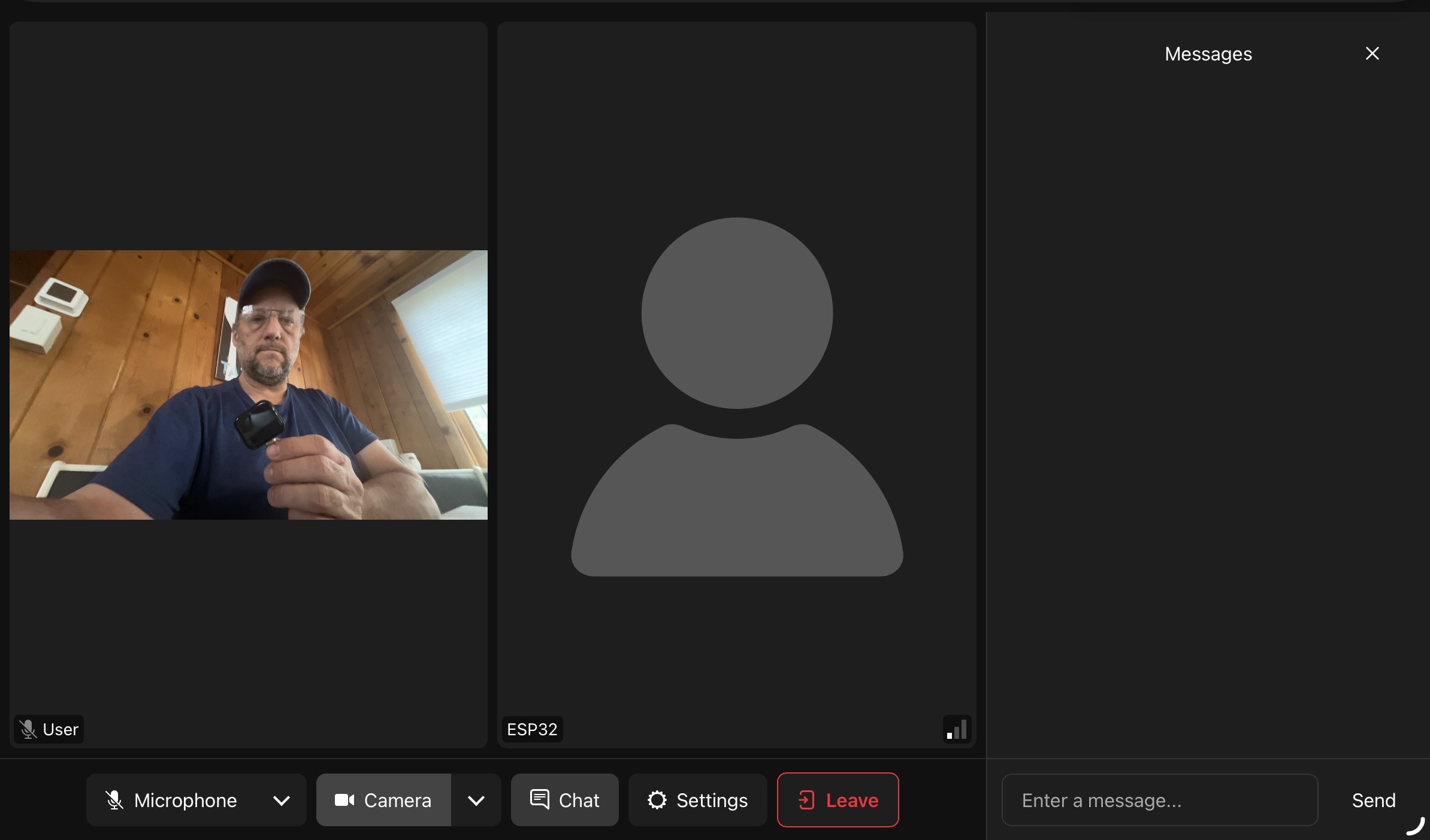
5.5 Test with your browser#
Open LiveKit Meet in your browser and join the same room. Speak into your browser mic and hear it through the ESP32 speaker; speak near the ESP32 mics and hear it in your browser. This confirms the audio pipeline is working end-to-end.
5.6 Connect to a voice agent#
The browser test proves the hardware works, but the real goal is to have your ESP32 talk to an agent. Any LiveKit agent that joins the same room automatically exchanges audio with the ESP32 — no changes needed on the device side.
Follow the Voice Agent Quickstart to create a Python agent. When you run it and point it at the same room, it receives the ESP32's microphone audio, processes it through an LLM, and streams the response back to the speaker. Your ESP32 is now a dedicated hardware frontend for that agent — a smart speaker, a voice-controlled robot, or whatever you're building.
Because the ESP32 is just another participant in the room, you can swap agents, add more participants, or change the agent's behavior without touching the firmware. The hardware frontend and the agent backend are completely decoupled.
To end the session, press the reset button or power off the ESP32.
Troubleshooting#
Codec init fails (I2C NACK errors)
- Check the I2C address format. The
esp_codec_devdriver expects 8-bit (left-shifted) addresses. If you pass the 7-bit address from the datasheet (e.g.0x18), the driver right-shifts it to0x0Cand talks to the wrong device. Use the_CODEC_DEFAULT_ADDRmacros. - Check the PMU. If your board has an AXP2101 or similar PMIC, the codec power rail may need to be enabled first.
- Run an I2C bus scan. Probe every address from
0x03–0x77usingi2c_master_probe(). This tells you exactly what's on the bus and eliminates guesswork. See thei2c_bus_scan()function inboard.c.
No audio output (speaker silent)
- Check that
PA_CTRL(GPIO 46) is driven high. The ES8311 driver handles this viapa_pin, but only if you pass the correct GPIO. - Make sure a speaker is connected to the MX1.25 header.
No microphone input
- The ES7210 uses TDM mode. If you initialize the RX channel in standard I2S mode, you'll get silence.
- Confirm
I2S_ASDOUT(GPIO 10) is correct — this is the data line from the ES7210 to the ESP32.
WiFi won't connect
- The ESP32-S3 only supports 2.4 GHz WiFi. If your router broadcasts a combined 2.4/5 GHz SSID, the device may fail to connect. Try a 2.4 GHz-only SSID.
- If you edited
sdkconfig.defaultsafter already building, deletesdkconfigand rebuild:rm sdkconfig && idf.py build
Audio glitches or echo
- Make sure PSRAM is enabled and configured for octal mode (
CONFIG_SPIRAM_MODE_OCT=y). - The AEC source expects 4 TDM channels with
channel_mask = 1 | 2. If your board has fewer mic channels, adjust accordingly.
Adapting to your own board#
The process is the same for any ESP32-S3 board with I2S audio codecs:
- Read the schematic. Find the I2S pins, I2C pins, codec I2C addresses (remember: 8-bit for
esp_codec_dev), PA enable pin, and whether a PMU gates codec power. - Write a
board.c. Initialize in order: I2C → PMU (if needed) → I2S → codec drivers →esp_codec_devhandles. Exposeget_playback_handle()andget_record_handle(). - Everything above the board layer stays the same. The media pipeline, room connection logic, and LiveKit SDK don't care which board you're on — and neither does the agent on the other end.
The complete source code for this example is available in the ESP32 SDK examples.